Photo date 10/05,
© S.W. Aber.
|
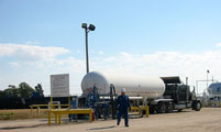
Photo date 10/05,
© S.W. Aber.
|

Photo date 10/05,
© S.W. Aber.
|
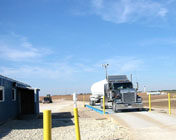
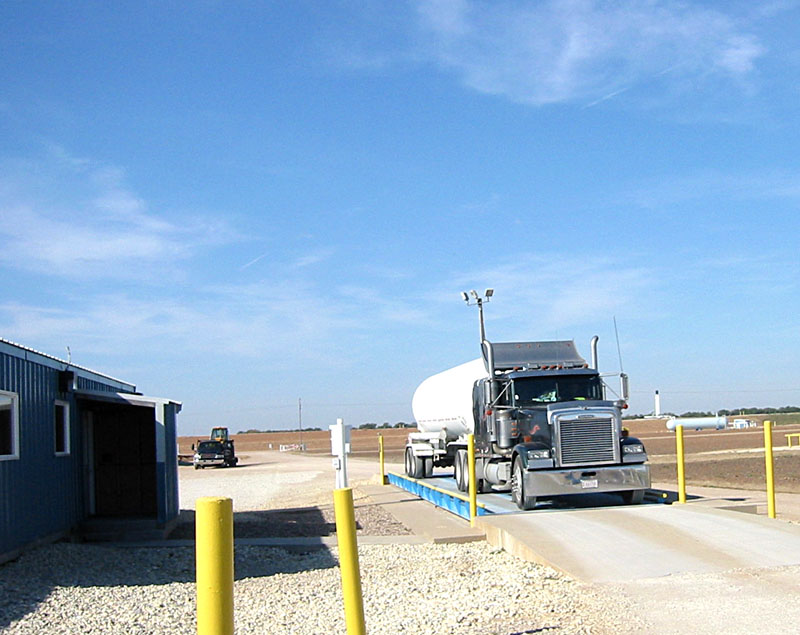
A tanker truck is being weighed when it enters the facility (above left). The product is being pumped into the tanker truck (center image) or can be pumped into tanker rail cars (above right). This facility is operating non-stop and workers have 12 hour shifts, 7 days of work and 7 days off (Darren Dick, personal communication, October 28, 2005). It takes approximately 15-20 hours to load 15 tanker trucks; the facility has 92 train cars for moving products as well (Dick).
|
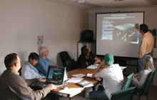
Photo date 10/05,
© Photo courtesy of Marcia Schulmeister.
|
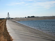
Photo date 10/05,
© S.W. Aber.
|
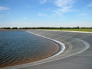
Photo date 10/05,
© S.W. Aber.
|
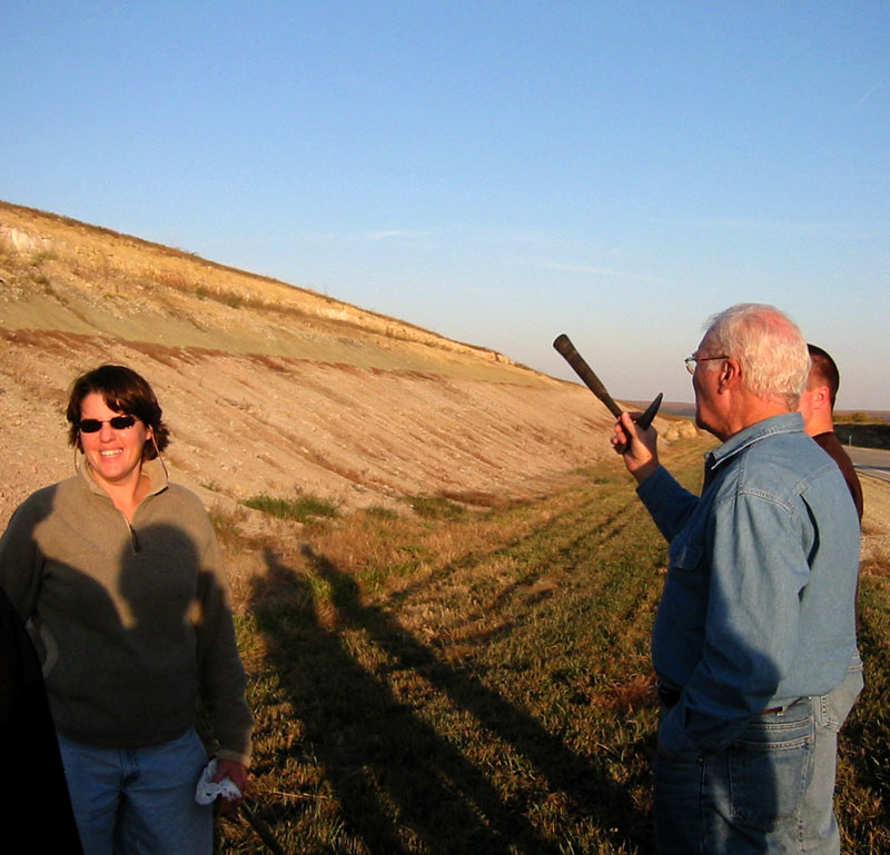
Kurt Shobe, a consulting geologist, provides background material to the group on salt dissolution and subsequent caverns. A sonar log provides the a 3-dimensional view of the cavern, defining cavern shape and storage capacity. Periodically this sonar device is lowered into the well with readings taken every 2 feet, and these data are imported to a GIS software program. The underground caverns are Christmas-tree shaped, wider at the bottom and narrower at the top; the width of the bottom chamber is 200-225 feet (Kurt Shobe, personal communication, October 28, 2005). These deep wells are in the Wellington Formation, below the groundwater table.
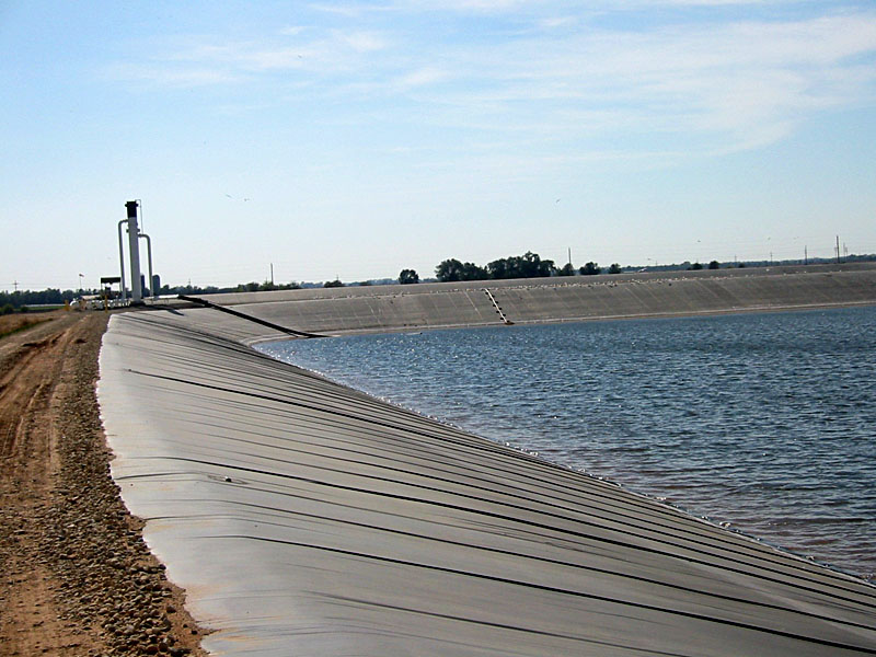
The Enterprise gas storage facility maintains 17 dissolution caverns and three brine ponds. One of three brine ponds is shown here. The brine ponds are constructed like a swimming pool, with a clay layer and double lined tarp laid into a basin which is then filled with brine. The lining keeps the salt water from polluting the groundwater and surrounding fields and vegetation. Although rainfall dilutes the brine, evaporation concentrates the brine and keeps it in balance. One inch of rain adds 15,000 barrels of fresh water; however, the brine is monitored and maintains a 99-100% salinity rate (Darren Dick, personal communication, October 28, 2005).
|
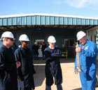
Photo date 10/05,
© S.W. Aber.
|
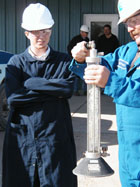
Photo date 10/05,
© Photo courtesy of Marcia Schulmeister.
|
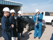
Photo date 10/05,
© Photo courtesy of Marcia Schulmeister.
|
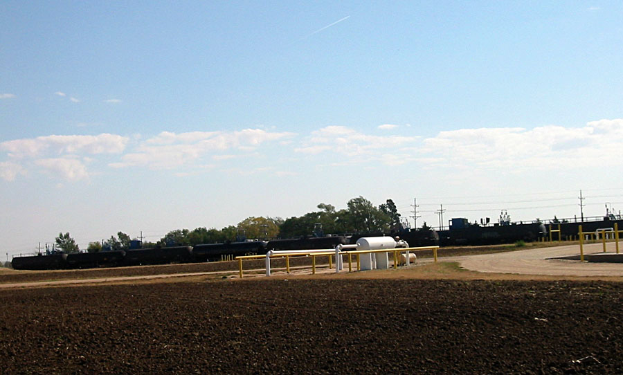
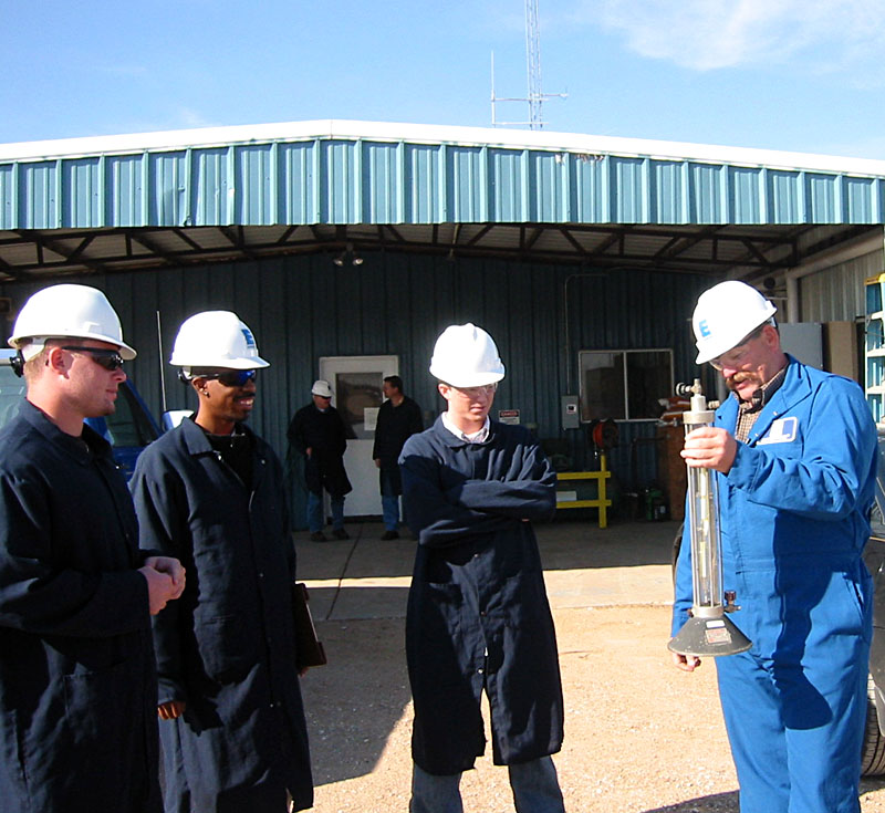
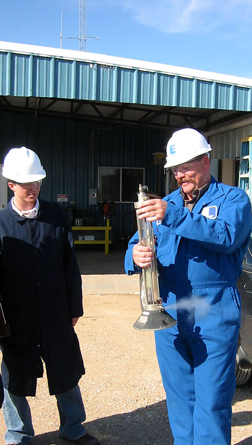
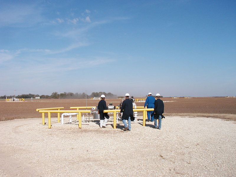
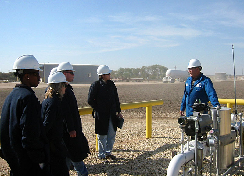
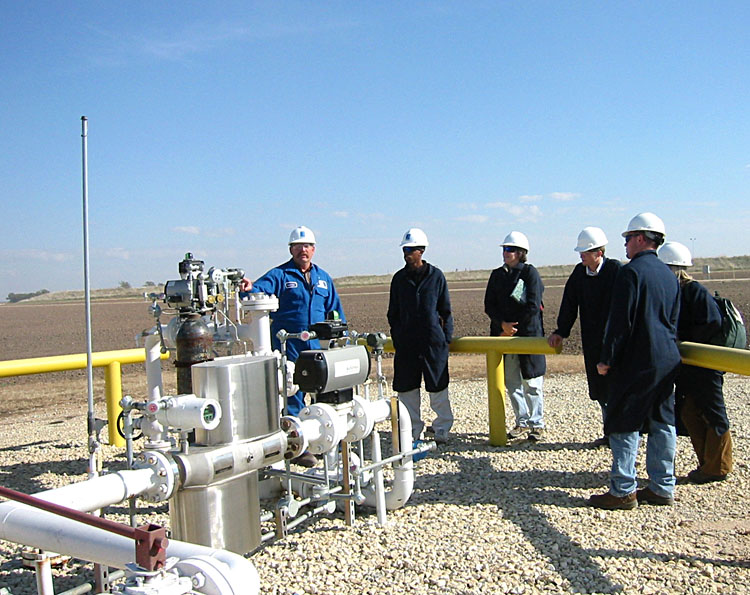
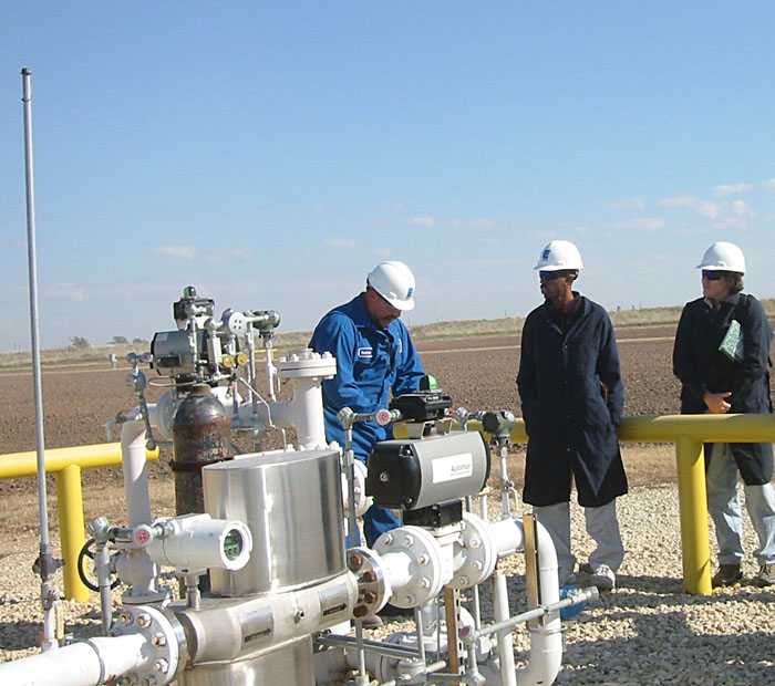
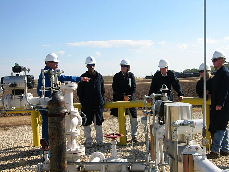
The well and pipeline system covers approximately 40 acres (Darren Dick, personal communication, October 28, 2005). Darren Dick, Enterprise Products Operating Manager, explains phase change that most light gases undergo as pressure changes occur (above left and center). The release of pressure changed the liquid hydrocarbon product to a gas in the clear tube. The students could feel the heat transfer that occurs during the phase change on the outside walls of the tube.
|
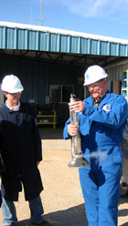
Photo date 10/05,
© S.W. Aber.
|
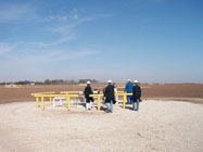
Photo date 10/05,
© Photo courtesy of Marcia Schulmeister.
|

Photo date 10/05,
© S.W. Aber.
|
New storage caverns are produced by drilling a borehole into the salt, installing three concentric well casing strings, and injecting fresh water into the outer casing to dissolve salt. The outer casing is cemented and sets 100 feet below the top of the salt formation, or approximately 775 feet below the surface, in order to provide strength to the cavern. The bottom of the salt layer is around 900 feet below the surface. As the salt dissolves creating a brine, the brine is pushed up to the surface through the outer well casing as the LPG storage product is pumped in through a different well casing. The product will float on top of any remaining brine in the cavern. In order to get the product out of the cavern, the brine is pumped back in, forcing the product back out to pipelines that can then be accessed for transport by truck or rail. The product comes out of the ground at a constant temperature between 58 and 60 degrees Fahrenheit. As Darren Dick explained the operation of the facility, a tanker truck left with the product (above right).
|
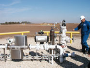
Photo date 10/05,
© Photo courtesy of Marcia Schulmeister.
|
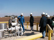
Photo date 10/05,
© Photo courtesy of Marcia Schulmeister.
|
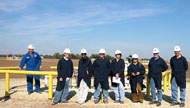
Photo date 10/05,
© S.W. Aber.
|
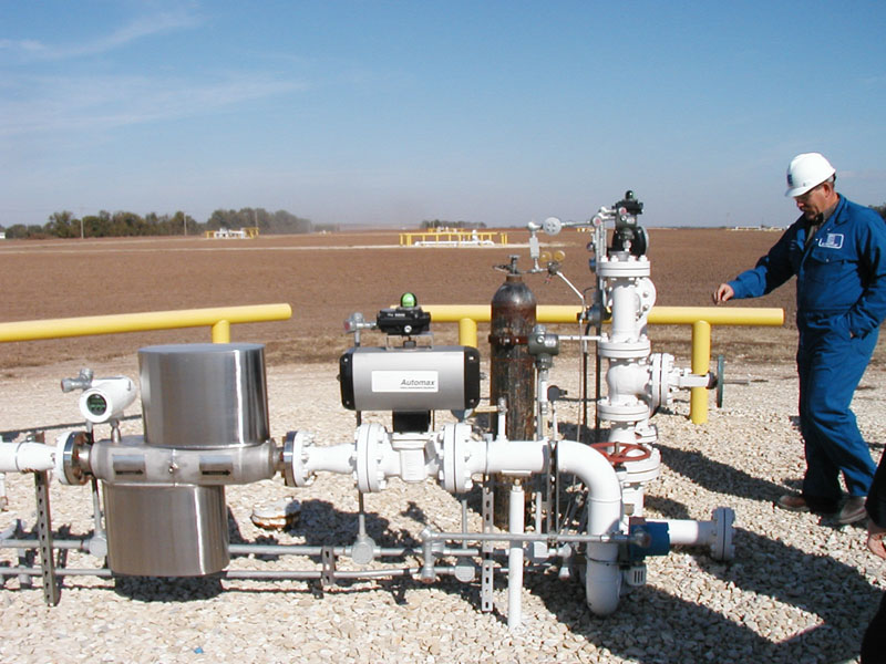
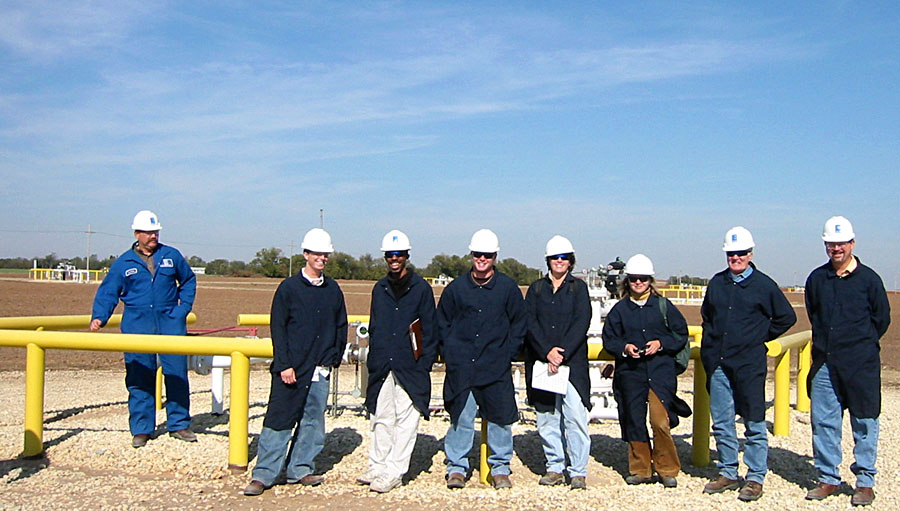
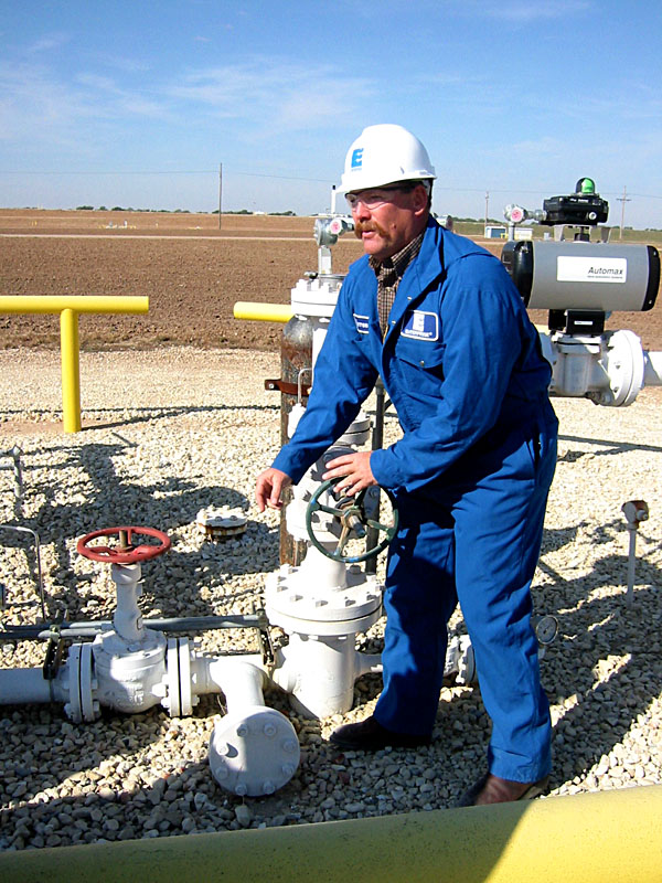
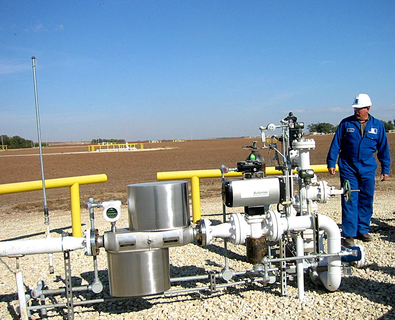
Above ground monitoring and transporting equipment are shown for one gas storage cavern (above left and center). In the image on the right, the ES 333 class and other participants included: Darren Dick; Tyler Ringler, ESU undergraduate Earth Science (ES) major; Kevin Barnett, ESU graduate ES major; John Waechter, ESU undergraduate ES major; Marcia Schulmeister, ESU Assistant Professor in ES; Elena Volkova, visiting Russian Fulbright scholar in residence at the Earth Science Department at ESU; Paul Johnston, ESU Professor Emeritus; and Kurt Shobe, Consulting Geologist from GeoStat Environmental LLC and ESU alumnus. The photographer is the webpage author, Susie Aber, who is a lecturer in ES at ESU.
|
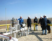
Photo date 10/05,
© S.W. Aber.
|

Photo date 10/05,
© S.W. Aber.
|

Photo date 10/05,
© S.W. Aber.
|
|
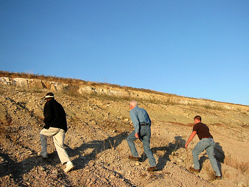
This dissolution of bedded rock salt to produce caverns for LGP storage is a unique and simple method. It was initially used for jet fuel storage at a nearby Air Force base during WWII (Kurt Shobe, personal communication, October 28, 2005). It is a cost effective way for large capacity storage; each cavern may hold from 200,000 to 380,000 barrels of the liquefied hydrocarbon product (Shobe). Also, it is safe in part because salt under pressure takes on a plastic consistency and if any cracks open up in the cavern, brine will infiltrate and seal off cracks in cavern walls. However, the caverns must be full at all times with brine and/or product so there is never a void.
|

Photo date 10/05,
© S.W. Aber.
|

Photo date 10/05,
© S.W. Aber.
|

Photo date 10/05,
© S.W. Aber.
|
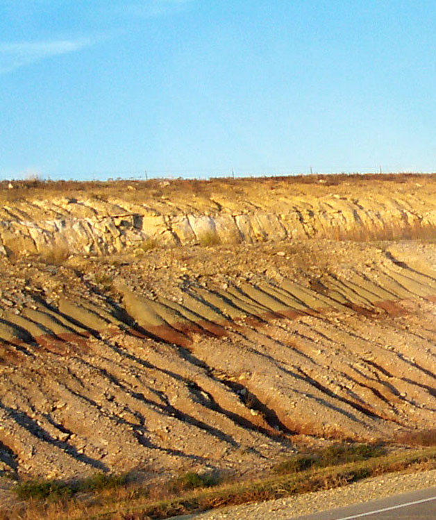
| Approximately 300 feet of shale sits on top of each well storage cavern and this creates the pressure necessary to keep the gas in a liquid state. There is a 100 foot salt layer above the caverns, which provides strength to the storage area because rock salt is stronger than the overlying shale (Kurt Shobe, personal communication, October 28, 2005). There is 300 to 400 feet horizontal distance between wells and a total of 640 storage wells in central Kansas (Shobe).
Customers may lease a well and cavern for a year at approximately $1.25-$1.75 per barrel (Darren Dick, personal communication, October 28, 2005). Farmers plant crops in the ground surrounding each well. The fall and winter seasons are the busiest times of the year for moving product.
|
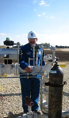
Photo date 10/05,
© S.W. Aber.
|
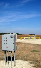
Photo date 10/05,
© S.W. Aber.
|

Photo date 10/05,
© S.W. Aber.
|
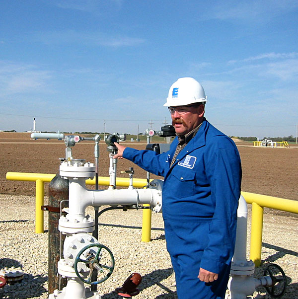
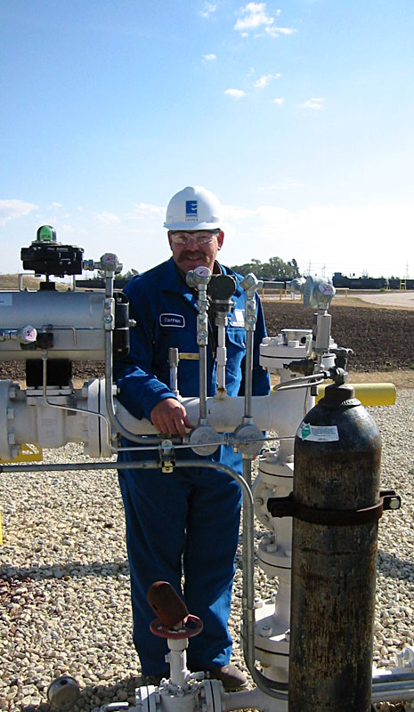
Safety is of utmost importance and the safety devices installed on each well can cost up to $100,000 (Darren Dick, personal communication, October 28, 2005). In the above left image, Darren is pointing out the small piece of lead inserted in the tubing; if there is a fire, this lead melts and closes the valve, thus shutting down the system.
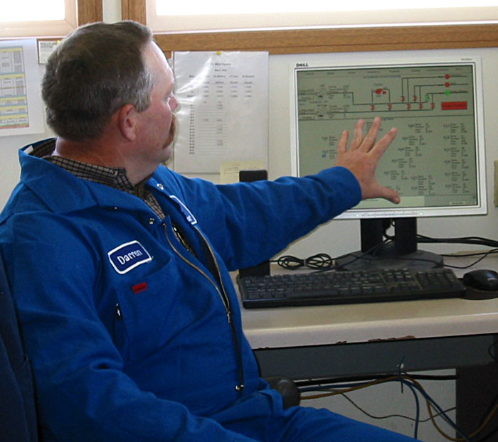
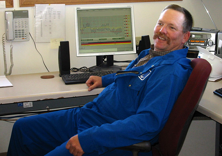
Many of these wells are from the 1970s and all wells are monitored continuously for chloride and combustible gases. Quarterly reports are sent to the Kansas Department of Health and Environment (KDHE). The above center image shows the radio controlled device that sends data from the well head to computers inside the facility. Different reports on activities can be generated on demand for any time and provided to the KDHE, parent company, or customer (above right).
|
|

Photo date 10/05,
© S.W. Aber.
|
|
Enterprise has been cleared and permitted for new wells, which will be the first drilled since the early 1990s. It takes approximately one year to prepare a new storage cavern, from drilling and dissolving to placing the product and brine lines from the well to the loading areas and brine ponds. A plastic tarp is laid down and all activity takes place on this tarp such as driving the drilling rig onto the tarp to prevent any pollution accidents. This rather unique use of salt in the mid-continent appears to be a relatively safe and effective way to store and move valuable energy resources.
The September 7, 2005 issue of the Hutchinson Kansas Chamber of Commerce, www.hutchchamber.com/outlooks/Sep2005/Sept7Issue.htm, reported a change in ownership of this facility, from Ferrellgas - Hutchinson to Enterprise Products Partners LP. The current name for the Hutchinson location is Enterprise Products Operating. For information on the parent company, visit the Enterprise Products http://http://www.epplp.com/index.html.
|


 For information about hydrogeology and environmental geology at ESU, visit webpages by Marcia Schulmeister at